How To Trigger a Modbus Write From an Input Control Block
This guide extends the Industrial Equipment Monitor Template and provides a multi-tenant example of triggering a command on an Edge Compute Device from an Experience.
Prerequisites
Before you begin, you need:
- A connected Edge Compute Device with the Gateway Edge Agent installed.
- Familiarity with Edge Computing and Modbus.
- A Modbus-enabled device.
- Familiarity with the Industrial Equipment Monitor Template.
How it Works
When complete, you will have implemented the following logic within an application:
- An Experience User accesses a dashboard page within an Experience.
- The Experience User clicks the button trigger within the Input Control Block.
- The Input Control Block triggers an Application Workflow.
- The Application Workflow verifies whether the user can perform this action using device association. If so, the workflow issues the Device Command.
- The Device Command triggers an Edge Workflow that performs the Modbus write.
Let’s start building!
Starting from a Template
First, create an Application from the Industrial Equipment Monitor Template.
To learn more about the template, see the Application README and the Deeper Dive Webinar Series: Industrial Equipment Monitor Application Template Replay.
Edge Workflow
To begin, you must first create an Edge Workflow.
Device Commands can trigger an Edge Workflow using the Device: Command Trigger. Here is the Edge Workflow you will build::
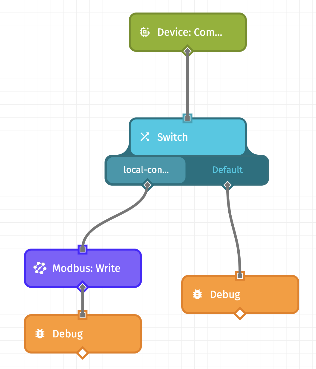
While using the Device: Command Trigger, all commands for the devices configured, regardless of name and payload, will trigger any Edge Workflow with the Device: Command Trigger. However, you can use a Switch Node and the name of the command to perform a unique action per the command name.
In this case, you are going to configure the workflow to respond to a command with the name of local-control.
Step One: Create the Edge Workflow
To create this Edge Workflow:
- Drag the Device: Command Trigger onto the workflow canvas. This enables the workflow to listen for device commands.
- Connect a Switch Node to the Device: Command Trigger. This enables you to configure different commands for your device.
- For the
local-controlcase of the Switch Node, connect a Modbus: Write Node. - Connect a Debug Node to the Modbus: Write Node. This displays the payload in the Debug Panel.
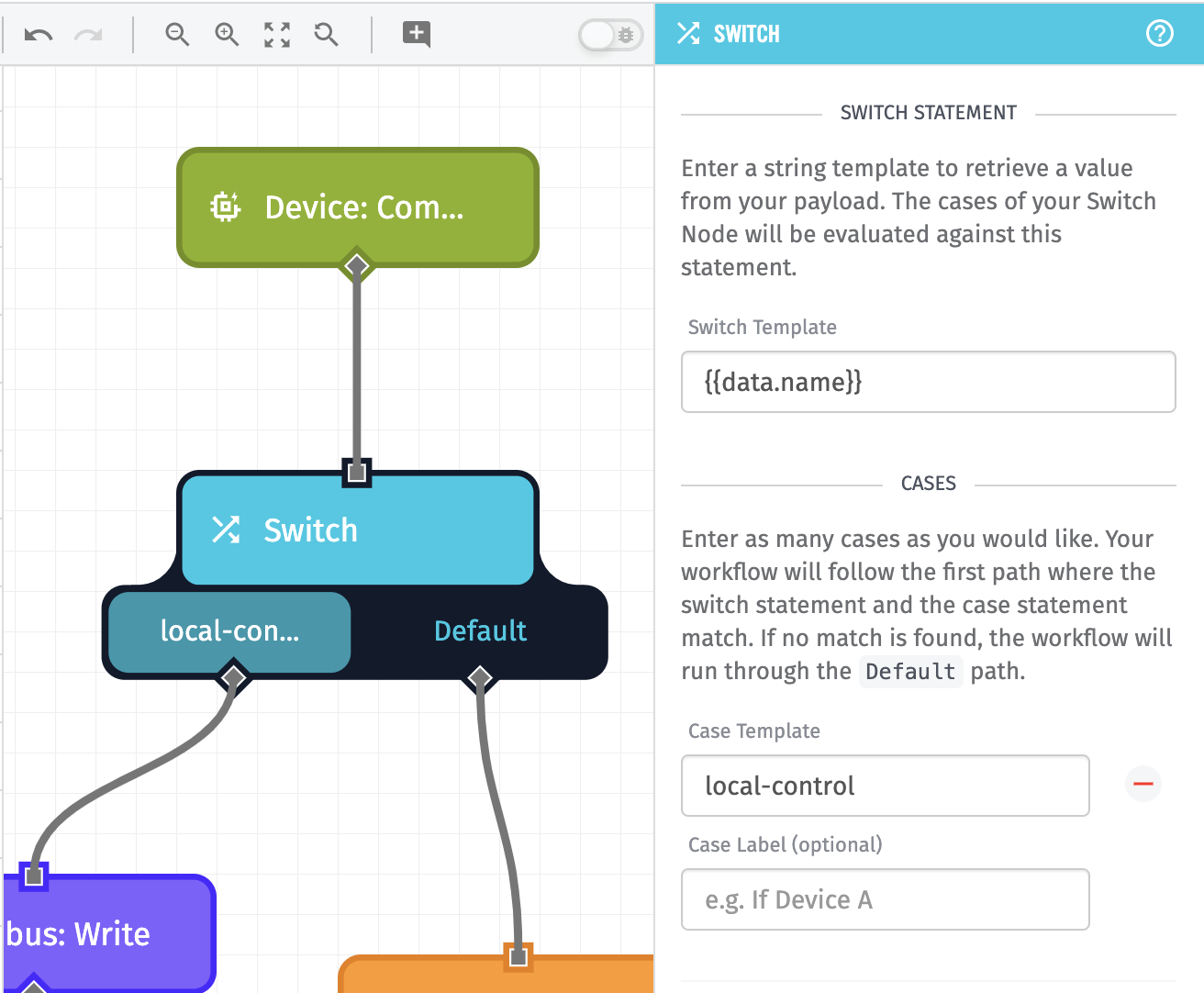
Step Two: Configure the Switch Node
To configure the Switch node, using the local-control command:
- Enter
{{data.name}}as the “Switch Template.” - Enter
local-controlas the “Cast Template.”
Step Three: Configure the Modbus: Write Node
Next, you’ll configure the Modbus: Write Node. Since the configuration is device-specific, refer to your device manufacturer’s documentation and the Modbus Write Node documentation.
In production applications, it's common to store device configuration as device tags. Using tags, you may store the Modbus configuration (hostname, IP, port, etc.) on the device itself.

The gateway on the device is set up as an Edge Compute Device within Losant. The devices the Gateway Edge Agent communicates with are commonly set up as Peripheral Devices. In this example, the peripheral is the Modbus-enabled PLC. You may access Peripheral Devices and their tags using the Peripheral: Get Node.
After the Peripheral Device is available on the payload, you may use these values within the Modbus configuration:
 "
"
Step Four: Deploy and Test Your Edge Workflow
The final step of configuring your Edge Workflow is to deploy and test. You can test your workflow with a Virtual Button without having to send a device command from a real device. Add the Virtual Button Trigger to your workflow, as shown in the image below:

Once you have a working Edge Workflow, you can move on to the next piece.
Application Workflow
From within a Dashboard, when you press the button in the Input Control Block, it can be configured to “press” a workflow with a Virtual Button.
Next, you need to create an Application Workflow that’s triggered with a Virtual Button Trigger.
Step One: Create an Application Workflow
Here is the workflow you will build:
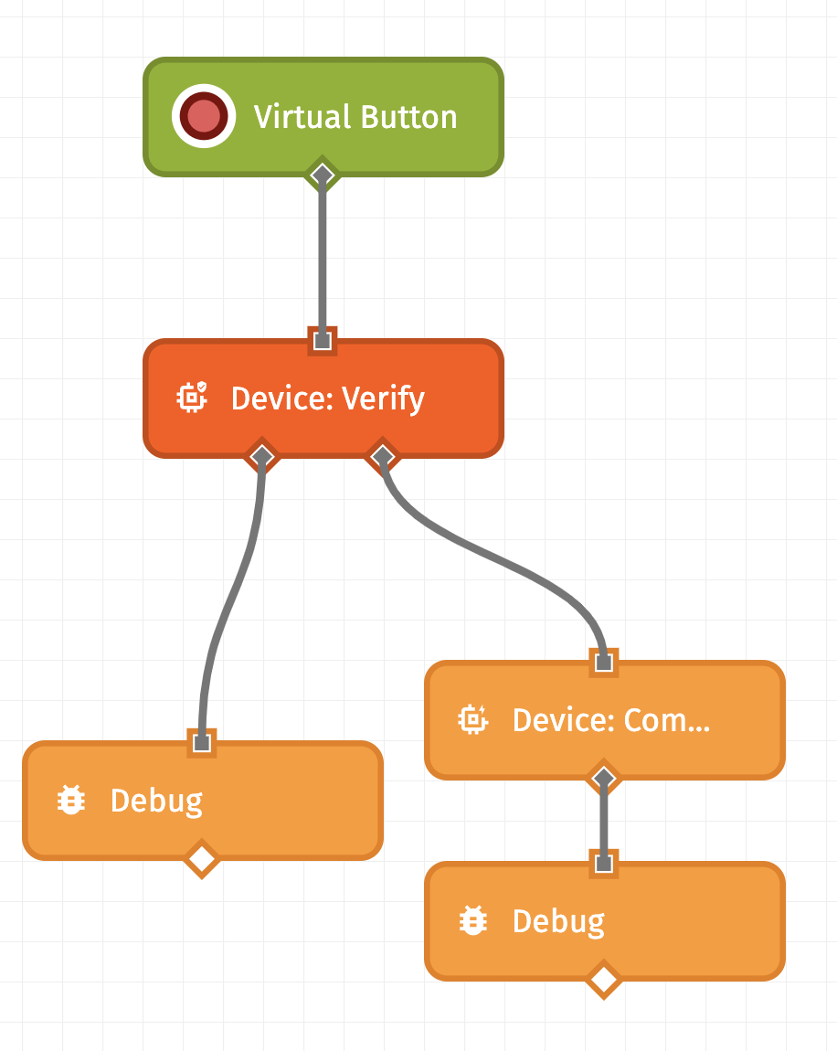
To create this workflow:
- Drag a Virtual Button Trigger onto the workflow canvas.
- Connect a Device: Verify Node to the Virtual Button Trigger. This allows a workflow to verify whether a device is associated with an experience user.
- Connect a Device: Command Node to the right (success) side of the Device: Verify Node. This sends the
local-controlcommand to trigger the Edge Workflow. - Connect a Debug Node to both the left side of the Device: Verify Node and the Device: Command Node.
Step Two: Configure the Device: Verify Node
When an Experience User presses the button trigger, they are issuing control to a physical device, which could be very dangerous. This should be protected. It’s best practice to check that an Experience User can perform an action before it occurs. By leveraging Experience Users & Experience Groups, you can verify device access.
Within this application, Experience Groups define which Users should be associated with one or more devices. Here is the group structure that's in your current application:

Users in the “Sadler-Isberg” group should not be able to control devices from the “Tekton Health” group. You can impose that restriction, or any additional requirements for your application, in this workflow with the Device: Verify Node.
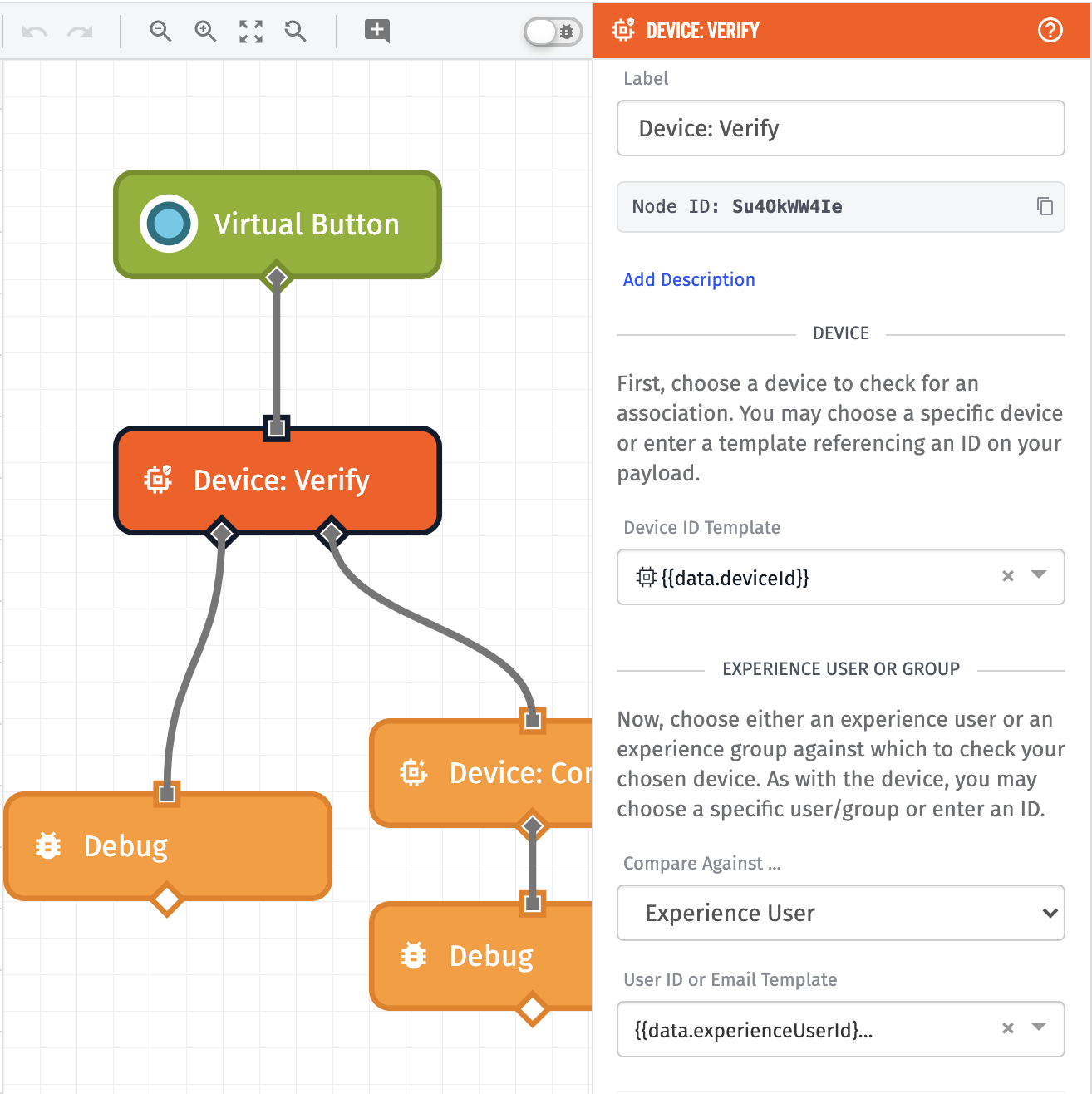
To configure this node:
- In the “Device” configuration, set the “Device ID Template” to
{{data.deviceId}}. - In the “Experience User or Group” configuration, set “Compare Against…” to
Experience User. - Set “User ID or Email Template” to
{{data.experienceUserId}}.
These values are obtained from the Input Control Block. Here, you are verifying that the user at {{data.experienceUserId}} is associated through Experience Groups to the device at {{data.deviceId}}. If this check was successful, the node will branch to the right to send the payload to the Device Command.
Step Three: Configure the Device Command Node
Next, configure the Device: Command Node to issue the local-control command.

To configure this node:
- Set the “Command Name Template” to
local-control. - Set the “Command Payload Type” to
JSON Template. - Set the “Command Payload JSON Template” to:
{
  "range": {{jsonEncode data.range}},
  "toggle": {{jsonEncode data.toggle}},
  "text": {{jsonEncode data.text}},
  "select": {{jsonEncode data.select}},
  "deviceId": {{jsonEncode data.deviceId}}
}
The values above are obtained from the Input Control Block. In practice, your Input Control Block could contain anything from a single button with no input, or a single button with various inputs.
Lastly, click "Save and Deploy" on your Application Workflow to save and deploy.
Input Control Block
Now that you have an Application Workflow with a Virtual Button to be triggered, you can set up your Input Control Block.
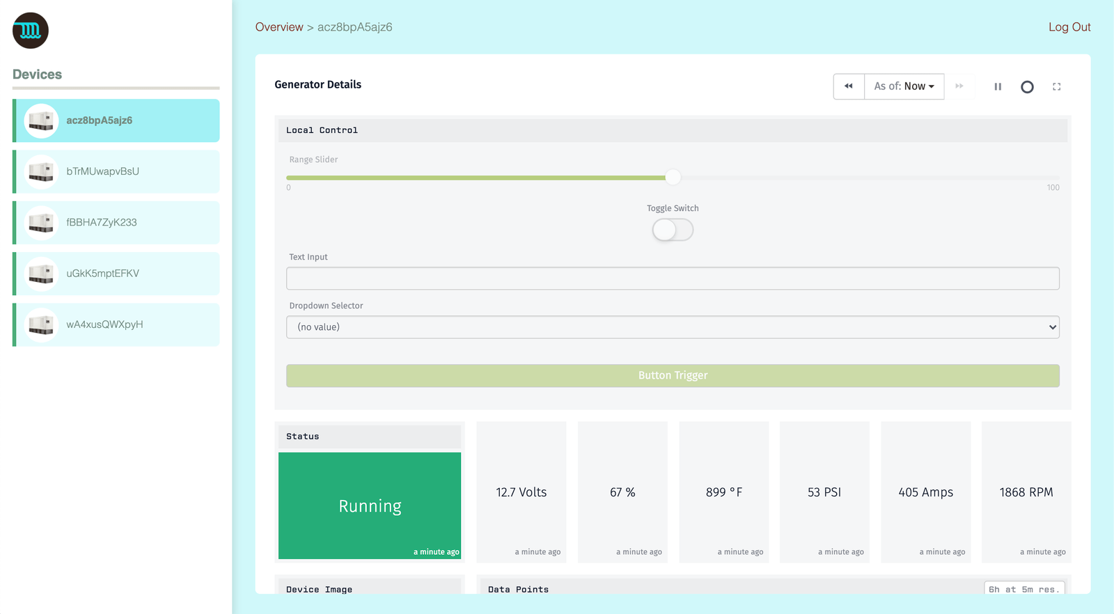
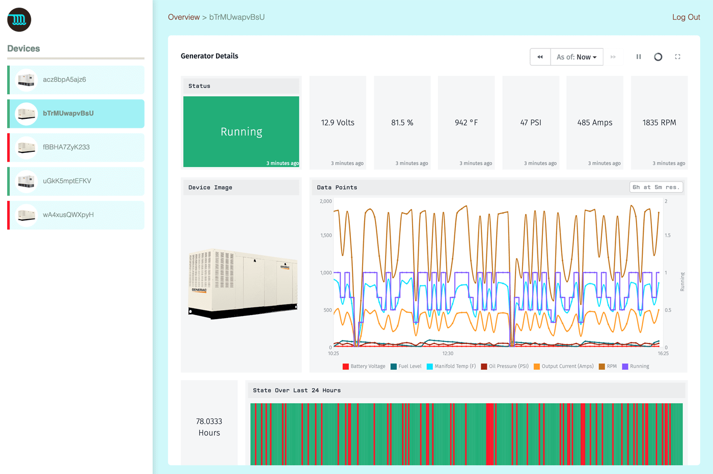
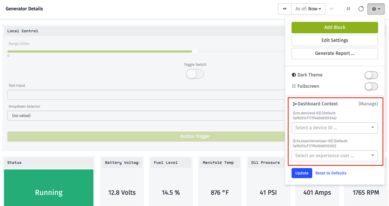
In the template, there is a dashboard called “Generator Details,” shown below:
This dashboard displays the telemetry information of a single generator. This is where you add the Input Control Block. This allows the user looking at this dashboard to initiate the local control of the currently viewed device.
This is the final result:
To configure an Input Control Block:
- Navigate to the “Generator Details” dashboard.
- Add an Input Control Block.
-
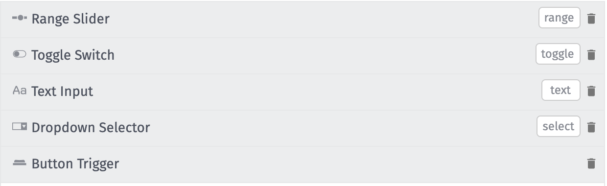
Configure the following inputs:
- A Range Slider and set the “Template ID” to
range. - A Text Input and set the “Template ID” to
text. - A Toggle Switch and set the “Template ID” to
toggle. - A Dropdown Selector and set the “Template ID” to
select.
- A Range Slider and set the “Template ID” to
-
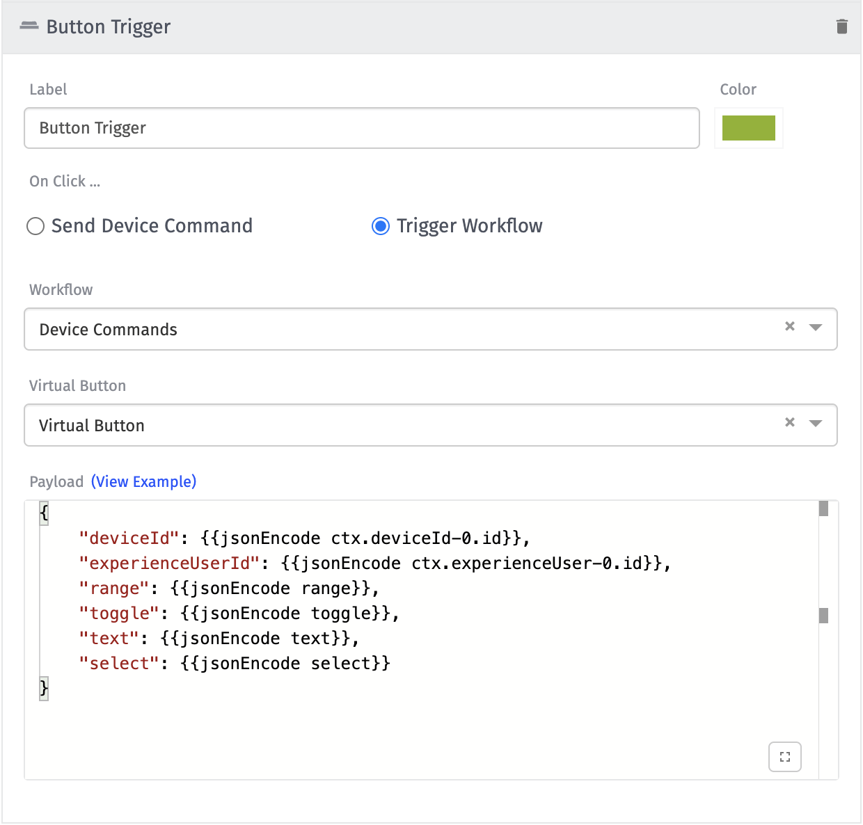
To configure the Button Trigger:
-
Set “On Click...” to “Trigger Workflow.”
-
Set “Workflow” and “Virtual Button” to be the Application Workflow created in this guide.
-
Set the “Payload” to:
{
  "deviceId": {{jsonEncode ctx.deviceId-0.id}},
  "experienceUserId": {{jsonEncode ctx.experienceUser-0.id}},
  "range": {{jsonEncode range}},
  "toggle": {{jsonEncode toggle}},
  "text": {{jsonEncode text}},
  "select": {{jsonEncode select}}
}
After configuring this block, an Experience User is able to configure the inputs and trigger the Application Workflow using the Button Trigger.
To test this workflow:
- Login to your Experience as an Experience User.
- Navigate to a device's "Generator Details" dashboard.
- Fill out the input controls.
- Click the button trigger.
The resulting payload should look like the following:
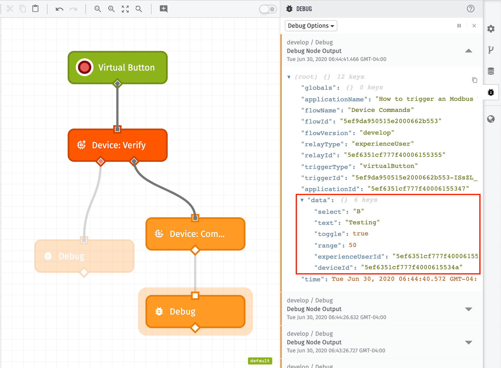
Context Variables
The variables range , text, toggle, and select come from the Input Control Block directly. However, deviceId and experienceUserId come from Context Variables. The “Generator Details” dashboard is configured with two context variables:
- Device Context Variable: Represents the device the dashboard is currently presenting.
- Experience User Context Variable: Represents the Experience User currently viewing the dashboard.
To learn more about Context Variables, refer to the documentation or Losant University.
To view how these are configured, refer to the “Generator Details” Dashboard Page configuration. Now, because Context Variables are available in the block settings, you can make use of these values:
{
  "deviceId": {{jsonEncode ctx.deviceId-0.id}},
  "experienceUserId": {{jsonEncode ctx.experienceUser-0.id}},
  ...
}
When the Input Control Block is triggered, you have the following information:
- The device to send the command to.
- The user who attempted to perform the command.
- Additional data from the Input Control Block to send to the device.
You are now able to log in to your Experience, trigger the Input Control, and trigger a Modbus: Write from the Cloud.
Was this page helpful?
Still looking for help? You can also search the Losant Forums or submit your question there.