Modbus: Read Node
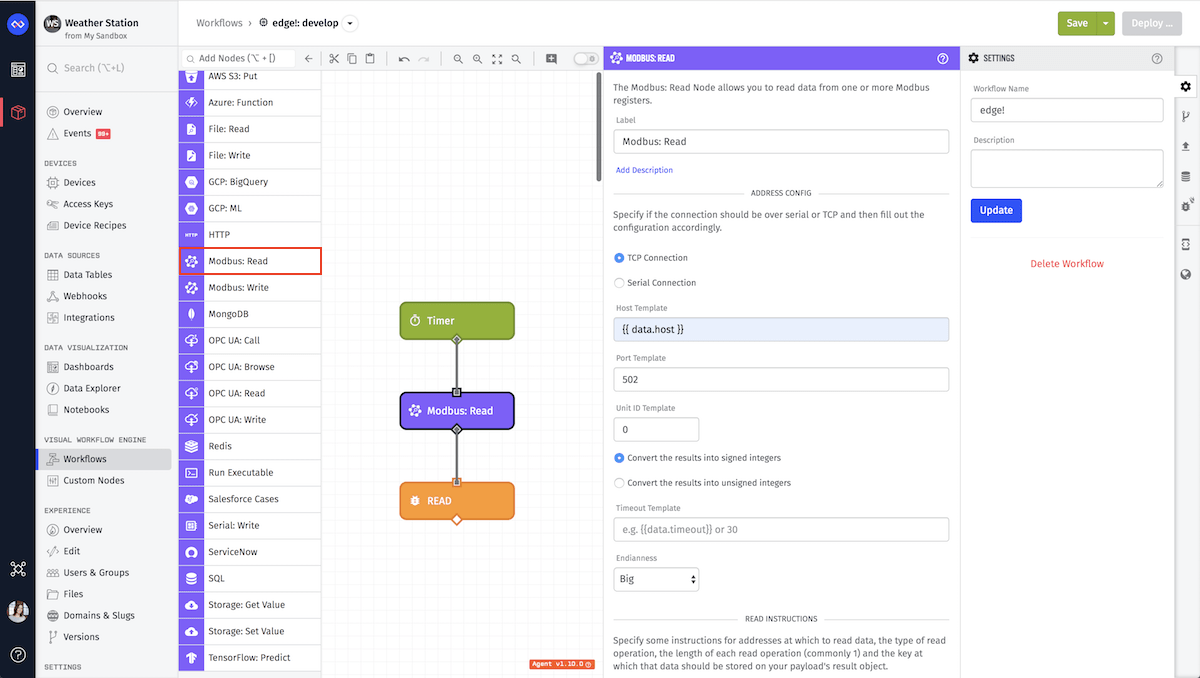
The Modbus: Read Node allows you to read multiple registers from Modbus-enabled PLCs. This node supports Modbus RTU and Modbus TCP and is only available in Edge Workflows. For more information on the Modbus Protocol refer to the Modbus documentation.

Node Properties
There are three main parts of the configuration for this node.

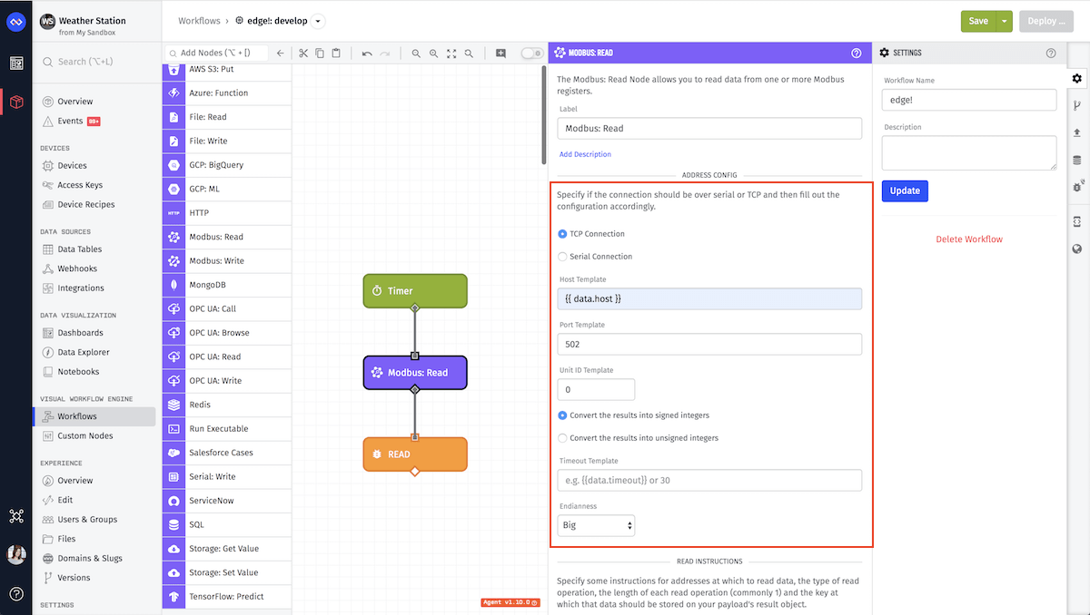
Address Configuration
Address Configuration contains five fields:
- Connection Type: This field can be
TCP Connection,Serial RTU ConnectionorSerial ASCII Connection. Depending on which type you select, different connection options will be available. For serial connections, here is more information on the difference between RTU and ASCII.
TCP Connection Configuration
- Host Template: (Required) A string template for the IP address at which the register(s) resides.
- Port Template: (Required) A string template or integer for the HTTP port.
Modbus RTU or ASCII Serial Connection Configuration
RTU Serial is only available on Gateway Edge Agent v1.10.0 and higher. ASCII Serial is only available on Gateway Edge Agent v1.46.0 and higher.
- Path Template: (Required) A string template or path that resolves to the serial port at which values will be read.
- Baud Rate Template: (Required) The baud rate, speed of communication over a data channel, which by default is
9600. This field can either be a integer or a template but it must resolve to a valid rate. For agent versions prior to 1.19.2 the following are the accepted baud rates:110,300,600,1200,2400,4800,9600,14400,19200,38400,57600,115200,128000,256000. As of agent version GEA v1.19.2 you may specify any positive integer for this field.
In GEA v1.10.0 the following options are defaulted:
- Data Bits:
8 - Stop Bits:
1 - Parity:
none.
However, in GEA v1.11.0 and higher, you may specify these options.
- Parity Template: The Parity is a method used to detect errors, which by default is
none. This field can either be a string or a template but it must resolve to one of the following valid options:none,even,mark,odd,space. - Data Bits Template: The Data Bits is the number of bits each character can be, which by default is
8. This field can either be a integer or a template but it must resolve to one of the following valid data bits:5,6,7,8. - Stop Bits Template: The Stop Bits is the bit sent at the end of ever character to signify the end of a character, by default this is
1. This field can either be a integer or a template but it must resolve to a valid stop bit. The only valid stop bits are1and2.
ASCII Serial Connection has one additional option.
- Start of Frame Character Template: The ASCII character that is the starting bit of the frame. This field defaults to
:.
Common Configuration
- Unit ID Template: (Required) A string template or integer for the Unit ID at the specified host and port. Defaults to
1. - Convert to signed or unsigned integers: The conversion of integer results to either signed or unsigned integers. Defaults to
convert to signed integers. - Timeout Template: A string template or integer for the numbers of milliseconds to wait before a timeout will occur while waiting for read results. Defaults to 30000 milliseconds.
- Endianness: The endianness, or sequential order of bytes. Defaults to “Big”.

Read Instructions
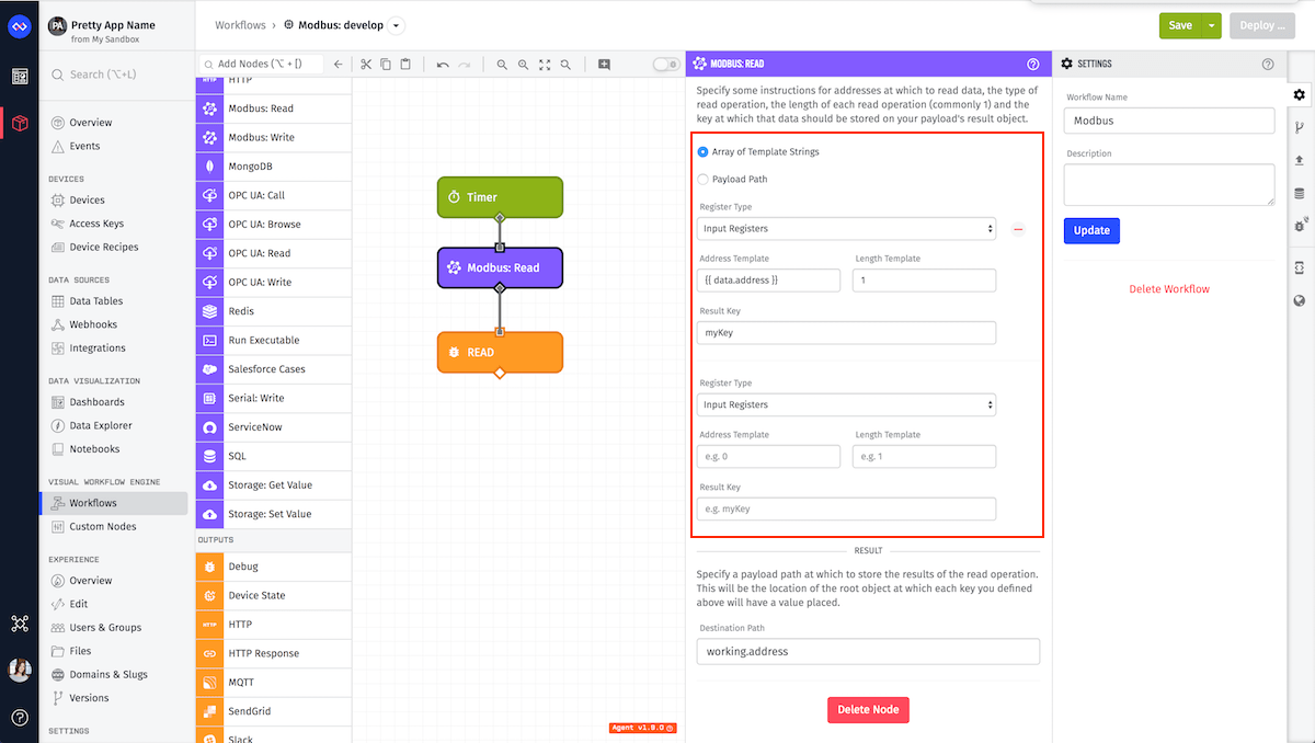
Read Instructions can be specified in one of two ways. At least one is required, but both can’t be specified at the same time.
-
Array of Template Strings: For each Read Instruction, fill out the following input configuration fields, all of which can utilize templates. You must define at least one instruction:
-
Type: (Required)
Input Registers: Read Input Registers (FC=04)Holding Registers: Read Holding Registers (FC=03)Coils: Read Coil Status (FC=01)Discrete Input: Read Input Status (FC=02)Read Device Identification: Read Device Identification (FC=43/14). This function is only available in GEA v1.16.0 and higher.
The following inputs are required for all the register types except Read Device Identification:
- Address: (Required) A string template or integer for the address at which to read. This should resolve to an integer between “0” and “65535” inclusive.
- Length: (Required) The length for this read instruction. This field is optional, but if set, it should resolve to an integer greater than “0.” Otherwise, the length defaults to “1”.
The following inputs are required only for Read Device Identification:
- Device ID Code: (Required) A string template or integer for the identification of the access level for the object ID. This should resolve to an integer between “0” and “4.”
- Object ID (Required) A string template or integer for the starting index of the device identification object. This should resolve to an integer between “0” and “255.”
- Result Key: (Required) The key at which to store the result of this read operation. This key exists on the Destination Path defined below. This can resolve to any string except “errors,” since that key is reserved for any errors that occur during reads. The value at this key is read as an signed integer.
-
-
Payload Path: (edge version 1.9.0 and above) Enter a payload path that resolves to an array of Read Instructions to be run on this node. The following are the object properties that each object in the array should contain for successful attempts:
- type: (Required) One of the following types:
input-register,holding-register,discrete-input,coilorread-device-identification. - address: (Required) An integer for the address at which to read. This integer must be between “0” and “65535.”
- length: An integer for the number of addresses to read, starting at the given address. This integer must be greater than “0.” Otherwise, the length defaults to “1.”
- deviceIdCode: An integer for the identification of the access level for the object ID. This integer must be between “0” and “4.”
- objectId: An integer for the starting index of the device identification object. This should resolve to an integer between “0” and “255.”
- key: (Required) The key (Result Key) at which to store the result of this read operation. This key exists on the Destination Path defined below the instructions. This can resolve to any string except “errors,” since that key is reserved for any errors that occur during reads. The value at this key is read as an signed integer.
- type: (Required) One of the following types:
The following is an example of an array that you could pass in:
[
  {
    "type": "holding-register",
    "address": 8,
    "length": 3,
    "key": "holdRegResults"
  }
]
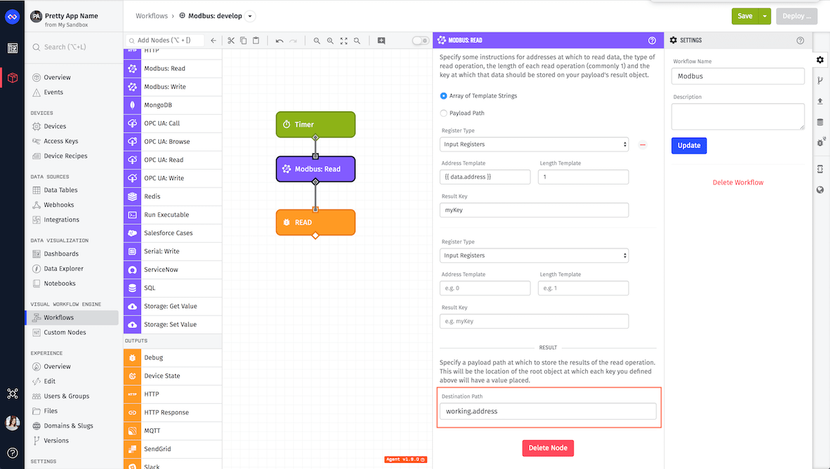
Destination Path

The results of each read instruction are placed in an object at the Destination Path (a payload path) at each instruction’s Result Key. All of the results are returned as an array except when reading the device identification. In the case of reading the device identification, the result is in the form of an object with two keys:
- Data: Data from identification description object
- Conformity Level: An integer representing the level of the device and the type supported access.
It is important that each key is named uniquely so the node does not overwrite another read result.
If the key is not present, the read failed, and there is a list of errors at the Destination Path under “errors.” For this reason, this node restricts Result Keys from resolving to the path “errors.” If one read fails, it does not mean that all reads will fail, rather, the reads continue until finished. The only time you get a single error for multiple reads is if the connection could never be made to the Modbus itself.
Node Example
The following is an example of a successful read, where an instruction’s Result Key is “threeCoils” and “deviceIdentification,” and the Destination Path is “destination.modbusOutput”:
{
  "destination": {
    "modbusOutput": {
      "threeCoils": [1, 0, 1],
      "deviceIdentification": {
        "data": {
          "0": "VendorName",
          "1": "ProductCode",
          "2": "MajorMinorRevision"
        },
        "conformityLevel": 1
      }
    }
  }
}
Processing Successful Results
The following is an example of using the Function Node to combine two Modbus read results and making them into one 32-bit float:
const modbus = payload.modbus
const buffer = new ArrayBuffer(4)
const view = new DataView(buffer)
view.setInt16(0, modbus.systemPressure[0], false)
view.setInt16(2, modbus.systemPressure[1], false)
payload.state = {
  systemPressure: view.getFloat32(0, false),
}
Node Errors
The following is an example of a failure to read, where a resultKey should have been threeCoils, and the destination path is destination.modbusOutput:
{
  "destination": {
    "modbusOutput": {
      "errors": [
        {
          "type": "MODBUS_READ_ERROR",
          "message": "Something useful to help you fix the issue."
        }
      ]
    }
  }
}
Related Nodes
Was this page helpful?
Still looking for help? You can also search the Losant Forums or submit your question there.
