Geofence Node
The Geofence Node allows a workflow to branch based upon whether a device reports state within a certain geographic area.
Configuration
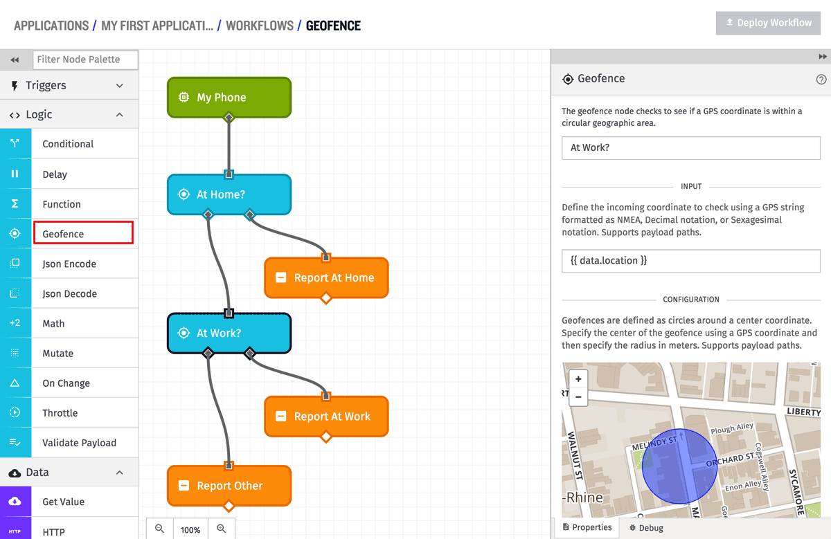
The Geofence Node has three different configuration settings: circular, polygonal, and polygonal path. The geofence has 3 configuration sections - the coordinate to check (the “input” coordinate), the geofence coordinates to check against, and a branch output.
Note: Embedded Workflows only support circular geofences.
Circular Geofence
When the Geofence Node runs, it calculates the distance between the input and center point coordinates, and if that distance is less than or equal to the defined center point radius, the true route on the right out of the node is taken. If that distance is greater than the center point radius, the false route on the left out of the node is taken. If the distance between the two points cannot be calculated for some reason, the false route on the left out of the node is taken.
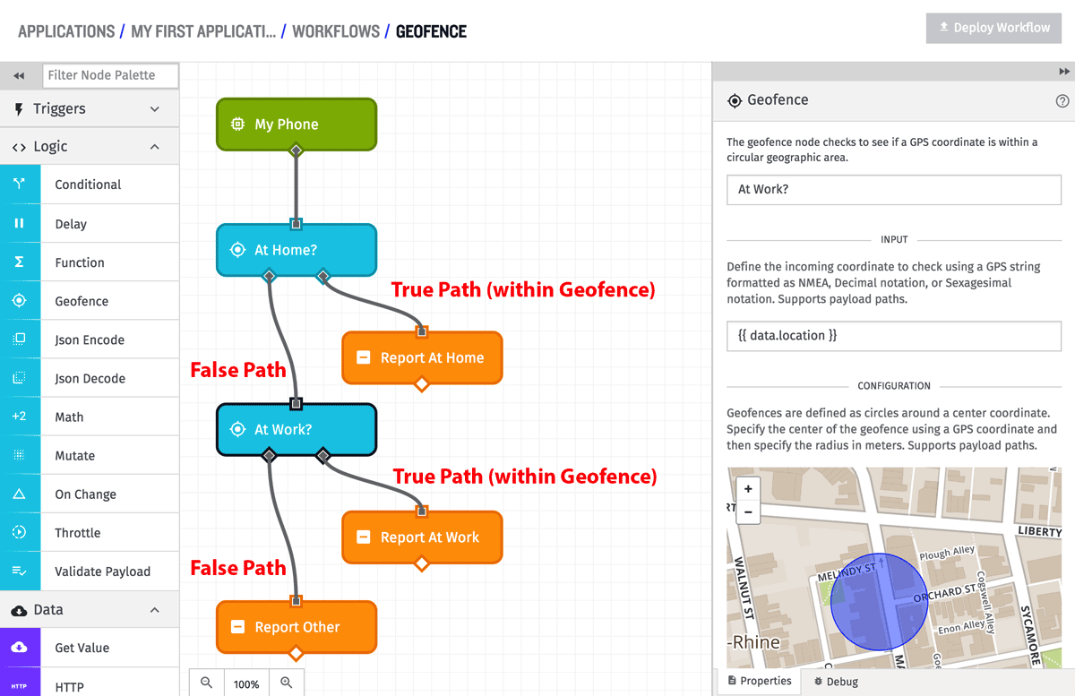
In the above example, there are actually two different geofences. The first checks against a center point position that represents “Home”. If that is true (the route to the right), it records that payload as being “At Home”. If that is false (the route to the left), it moves on to the second geofence, which checks against a center point position that represents “Work”. If that is true (the route to the right), it records that payload as being “At Work”, but if that is false (the route to the left), it records that payload as being “Other”.
Input Coordinate Configuration
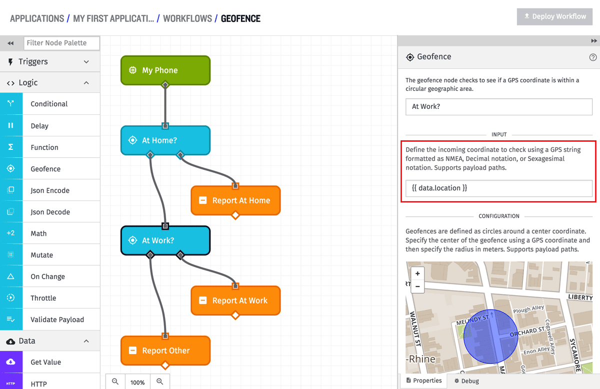
The input coordinates can be defined by any of the forms we support for GPS device state. No matter which form is used, the field will also accept a string template for the value. In the above example, the input coordinates are defined as the data.location field of the payload, which contains an NMEA string.
Embedded Workflow Formats
Embedded Workflows support different formats for defining GPS coordinates.
String templates must resolve to one of the following:
- An object containing
latitudeandlongitudekeys (e.g.{ latitude: 39.1025, longitude: -84.512 }). - An array whose first two elements are latitude and longitude respectively (e.g.
[39.1025, -84.512]).
String templates that resolve to comma-delimited coordinates or NMEA strings are not valid.
Center Point Coordinate Configuration
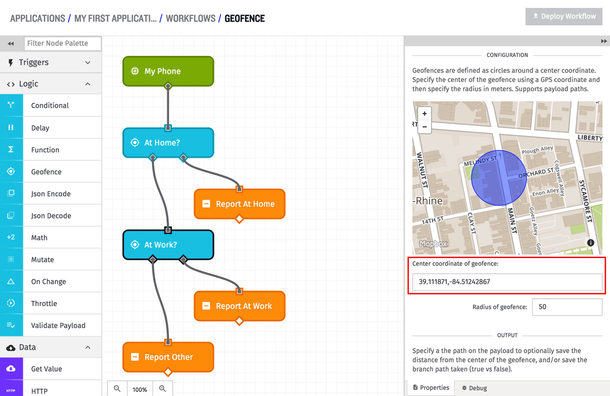
The center point coordinates can be defined the same way as the input coordinates, in any one of the forms we support for GPS device state. While in the common case, the center point coordinate values will be static, these fields also support string templates in case a dynamic center point is needed. Because the common case is a static center point, a map visualization is displayed to help show the real world location of the geofence. In the above example, the center point coordinates are defined statically using decimal degrees.
Radius Configuration
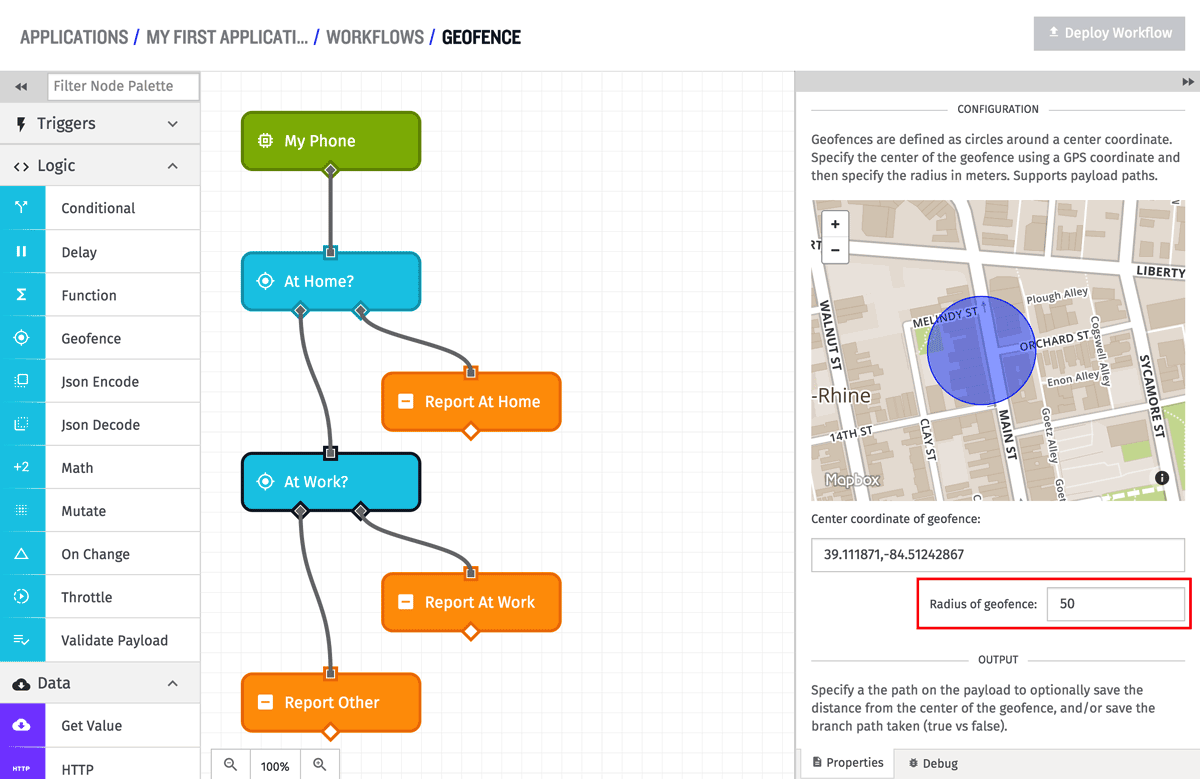
The radius of the center point is defined in meters, and must be greater than 0. If the radius is defined as 0 meters, only an exact match between the center point and input point will count as being “within” the geofence. In the common case, the radius will be defined as a static value, but the field does support string templates in case the radius needs to be dynamically defined based upon the current payload. If the radius (and center point) are defined statically, the map visualization will show the extent of the real world location of the geofence. In the above example, the radius is defined as 50 meters, and the map shows what that actually covers in the physical world.
Adding Distance or Branch to the Payload
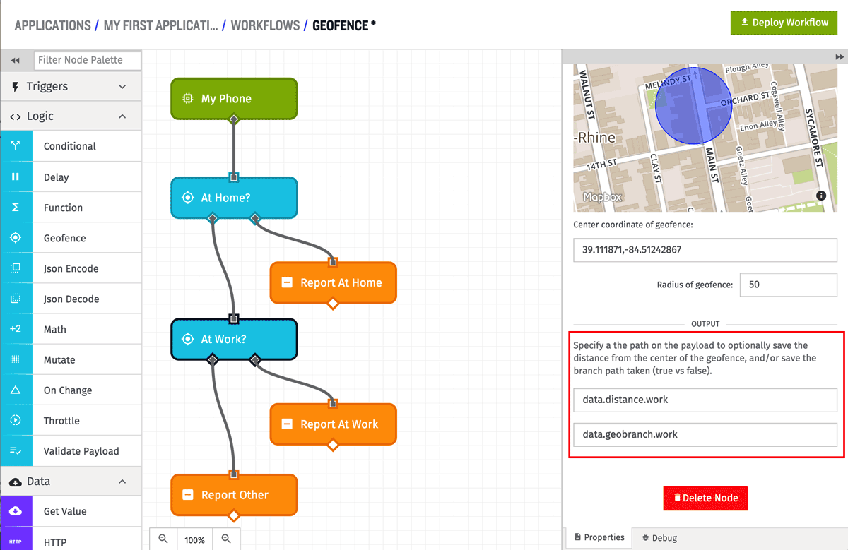
The Circular Geofence Node has the ability to optionally add the calculated distance between the input and center point to the payload at a defined payload path. If a path is defined, the distance (in meters) will be placed at that path no matter which branch out of the Geofence Node is taken. If there is a problem calculating the distance (bad coordinates or radius), no value will be places at the path. In the above example, the distance between the input and center coordinates will be placed at the data.distance.work path.
The node also has the ability to optionally add which branch out of the node was taken to the payload. If a path is defined, true or false will be placed at the given path, depending on which branch out of the node is taken. In the above example, the branch taken will be placed at the data.geobranch.work path.
So, for example, given the following payload:
{
  "time": Fri Feb 19 2016 17:26:00 GMT-0500 (EST),
  "data": {
    "location": "$GPGLL,3906.72686,N,8430.74572,W,231131,A,*2a",
    "distance": {
      "home": 1654
    }
  },
  ...
}
The payload after execution of the geofence node would look like:
{
  "time": Fri Feb 19 2016 17:26:00 GMT-0500 (EST),
  "data": {
    "location": "$GPGLL,3906.72686,N,8430.74572,W,231131,A,*2a",
    "distance": {
      "home": 1654,
      "work": 34
    },
    "geobranch": {
      "home": false,
      "work": true
    }
  },
  ...
}
Polygonal Geofence
Note: Embedded Workflows do not support polygonal geofences.
The Polygonal Geofence calculates whether the input coordinate falls within a defined polygonal area. If the input coordinate falls within the defined area, the true path is taken. If it falls outside the defined area, the false path is taken. If whether or not the input falls within the polygon cannot be calculated for some reason, the false route on the left out of the node is taken.
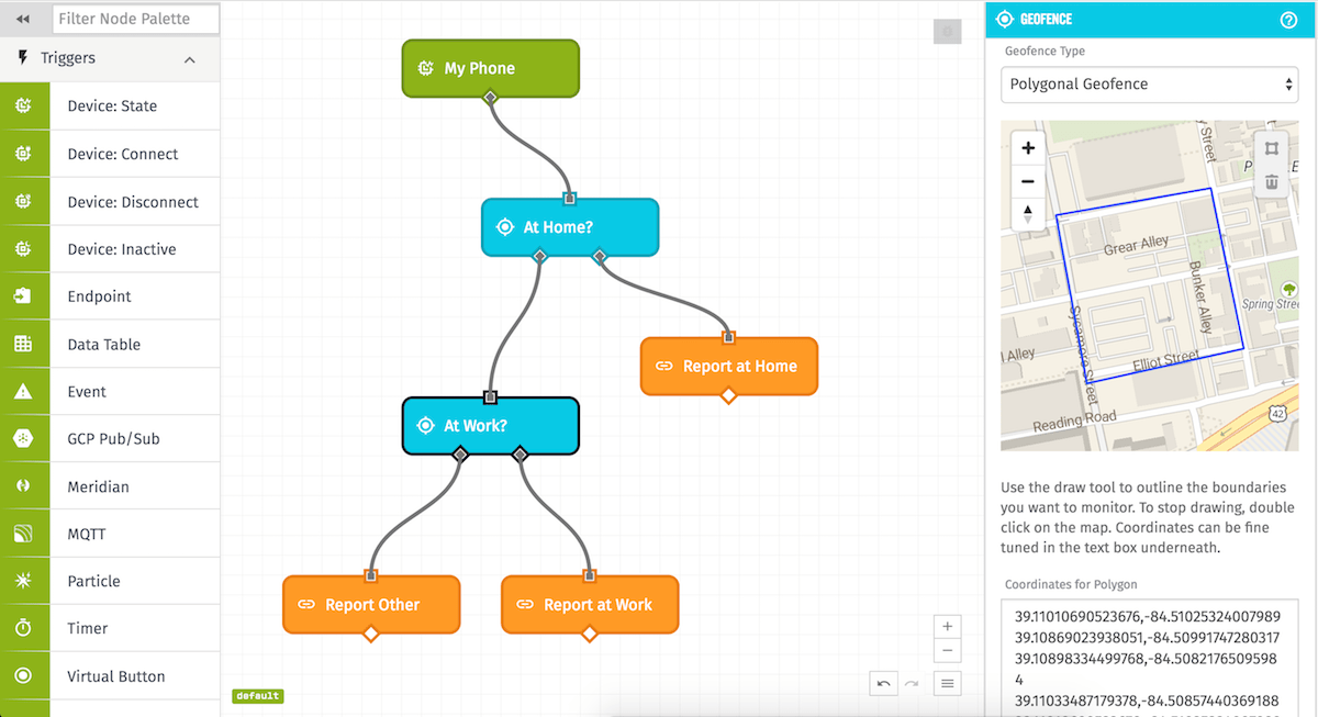
The Polygonal Geofence mode lets users draw their own polygon using the map’s drawing tool or by typing the coordinates into the text box below it using any of the forms we support for GPS device state.
To draw a polygon, click on the polygon tool in the top-right corner of the map and right-click where you’d like to begin to draw your polygon. To set the line and begin drawing in another direction, right-click on the map again. Do this until you have defined the area you with to monitor and then double-click to finish drawing. The coordinates of the drawn polygon will be placed in the text box below and can be edited and adjusted for more precision.
To delete a polygon, click inside of it and click the trash button in the top-right corner of the map or delete the coordinates in the textbox underneath the map.
Polygonal Path
The Geofence Node also allows polygonal geofences to be passed in via an array of GPS Coordinates defined on a payload path. Note the order of the points in the array is important, as it determines how the polygon is drawn.
Was this page helpful?
Still looking for help? You can also search the Losant Forums or submit your question there.
